INTRODUCTION
For the purpose of this course we are mainly concerned with general aviation aircraft, in other words aircraft that fly at 250 knots or below. At higher speeds there is the added complication of air compression which will be discussed in other courses.
There are four forces which act upon an aircraft:
- Thrust
- Lift
- Drag
- Weight
When an aircraft is on the ground, its weight is balanced by the reaction force of the ground, which acts through the wheels. Or, in other words, is supported by the ground.
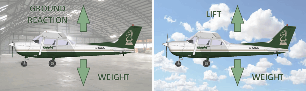
Whilst in level flight, the weight of the aircraft is balanced by the lift. Lift is generated by the flow of air over the wings. In addition, as aircraft move through the air it will experience a retarding force known as drag which, unless counteracted by an opposing force, will result in deceleration. In straight and level flight, the drag is balanced by thrust.
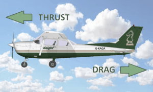
If the forces acting upon the aircraft are perfectly in balance, the resultant force acting on the aircraft is zero. This means that it will neither rise, fall, accelerate or decelerate. In this situation the aircraft is said to be in a state of equilibrium:
The WEIGHT is balanced by the LIFT
The DRAG is balanced by the THRUST
The aircraft will continue flying at the same velocity until a force acts upon it, for example, the pilot decreases thrust or a gust of wind pushes against the airframe.
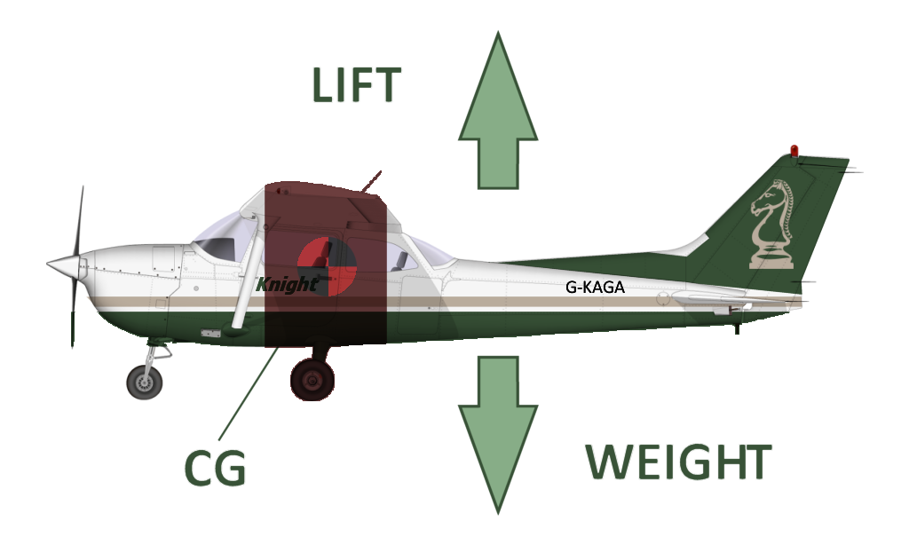
WEIGHT
Weight is the name given to gravitational force which, for the purposes of this course, refers to the total weight of the aircraft. This weight can be considered to act as a single force through the aircraft Centre of Gravity (CG). The CG can be defined as the point of balance and its position depends on the individual parts and loading of the aircraft. Aircraft manufacturers ensure that the operating band of the CG allows for the aircraft to remain within safe limits as it gets lighter during flight through a reducing fuel load.
The magnitude of the weight is also important and manufacturers specify maximum limits, for example the maximum take off weight (MTOW). These limits depend on both the structural strength of the aircraft and the operational requirements it is designed to fulfill.
The location of the CG depends on the magnitude and location of the weight and so changes as the distribution of the load changes. This occurs as the fuel load reduces or, for example, passengers move around or parachutists leave the aircraft. Therefore, weight and balance must be considered as part of the flight planning process. If either limitation of the weight or balance are exceeded the safety of the aircraft is compromised.
The definition describing a load that wings are able to support is wing loading. This is simply the weight per unit area:
Wing Loading = Aircraft Weight ⁄ Wing Area
Example: An aircraft has a maximum certified weight of 1220kg and a wing area of 20 square metres. What is the wing loading?
Wing Loading = Weight ÷ Wing Area = 1220/20 = 61kg/m2
LIFT
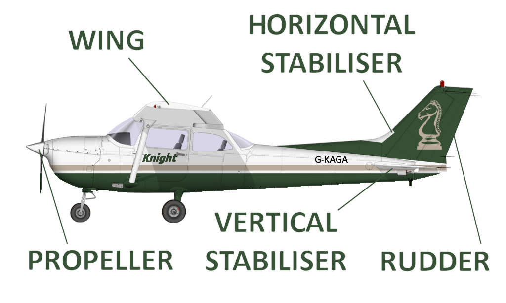
An aerofoil is a surface designed to aid lift, control or propel an aircraft by making use of airflow. The most common of these are the wing, horizontal and vertical stabilisers, rudder and propeller blades.
Control surfaces are components of the aerofoil. A pilot can manipulate these surfaces to adjust the shape of the aerofoil and the forces generated by the airflow over it and control the direction or momentum of the aircraft. These control surface will be discussed in detail later in this course. For this section we will focus on the wing and its purpose in providing lift.
Daniel Bernoulli, a Swiss scientist, explained the production of lift force from his discovery of the venturi effect.
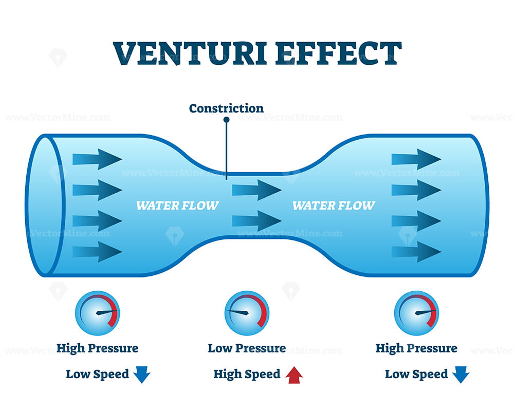
The Bernoulli’s Principle states:
“if the speed of a fluid increases, then either its static pressure must decrease to compensate, or its potential energy must decrease.”
In simple terms in relation to aircraft, if the airflow over a wing is faster (lower pressure) than the airflow below the wing (higher pressure) then lift will be generated pushing the wing, and therefore the aircraft, upwards. To this end, all wings are designed with a curved upper surface and a flatter lower surface to a lesser or greater extent. This creates the required difference in air pressure resulting in lift.
We shall discuss wing structures in greater detail in the Airframes course but, for now, we need to understand the basics of wing design. All wings have 3 main features:
- Camber: The curvature of the wing. More camber generally means more lift, but it can also increase drag.
- Chord Line: An imaginary line connecting the leading edge to the trailing edge of the wing. This line is crucial for measuring angles and understanding airflow.
- Angle of Attack: The angle between the chord line and the oncoming air. Increasing this angle can increase lift up to a point, but too much can lead to a stall.
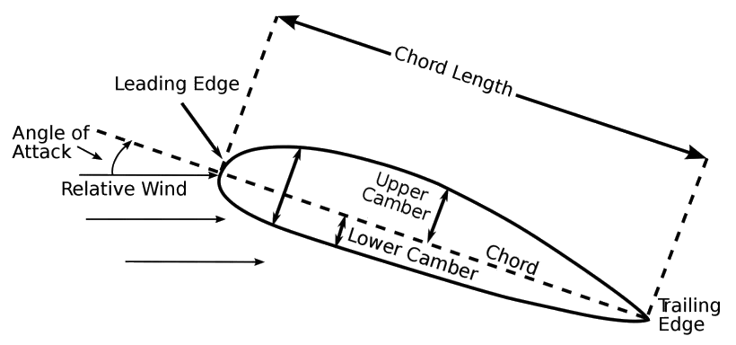
The design of the wing is crucial for effective lift generation. The following components play significant roles:
- Leading Edge : The front edge of the wing that first makes contact with the air.
- Trailing Edge : The rear edge of the wing where the airflow separates.
- Upper Surface : Curved surface that helps create the lower pressure above the wing.
- Lower Surface : Flatter surface the maintains higher pressure beneath the wing.
- Angle of Attack (AoA)
The lift force is perpendicular to the relative airflow with the total reaction resolved into two components. The drag force, which opposes motion and acts parallel to the relative airflow, and the lift force which is perpendicular to the relative airflow and the flightpath of the aircraft.